|
Deprecated
|
Prototypes
These early prototypes were for pre-1.0 releases and are used soley in our travel trailer. No further designs like this are in development. These prototypes were built with unfinished wooden boxes purchased at a hobby store. The components were laid out by hand, outlined and then cut-outs made with a Dremel tool. The boxes where then stained, the components inserted and cabling attached. In some places, breakout boards were used to supply power from a single power switch. Remember: the intent with these devices is to have the PiBox Media System provide media to wireless-connected PiBox Media Player's. The Media Player then plays videos through its projector. As an alternative, the use of SMB/NMB protocols makes the server's media available to both Android and iOS devices as well, provided they have a suitable app installed. Additional images are available in the PiBox Gallery. Future PiBox development plans include apps for both Android and iOS to display a similar UI for media selection as the PiBox Media Player. PiBox Media System
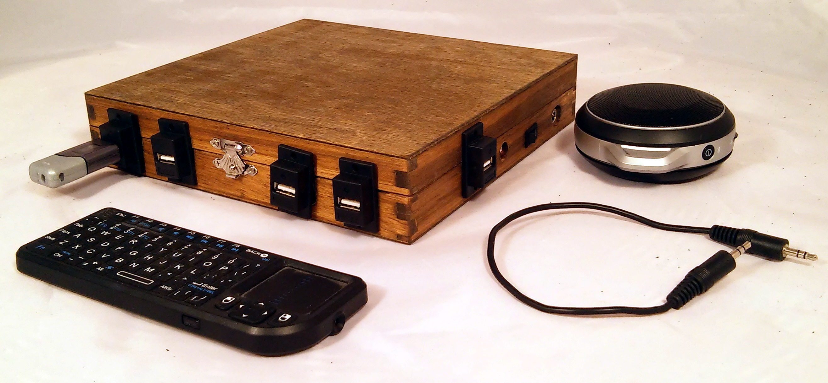
The PiBox Media System prototype case contains a UUGear 7-port USB hub mounted on a Raspberry Pi Model B that is fitted in the bottom half of a plastic case (which I think I got from Adafruit or Element14). This image shows the outside of the case with 4 USB ports on the front and 1 on the side. Two other ports are used internally for wifi and the USB keyboard/mouse (shown here in front of the case). Audio is designed to come out of the audio port of the Raspberry Pi but I switched it for my own use to use the audio from the HDMI port because the small 7" display I'll be using supports HDMI audio, and that's one less cable.
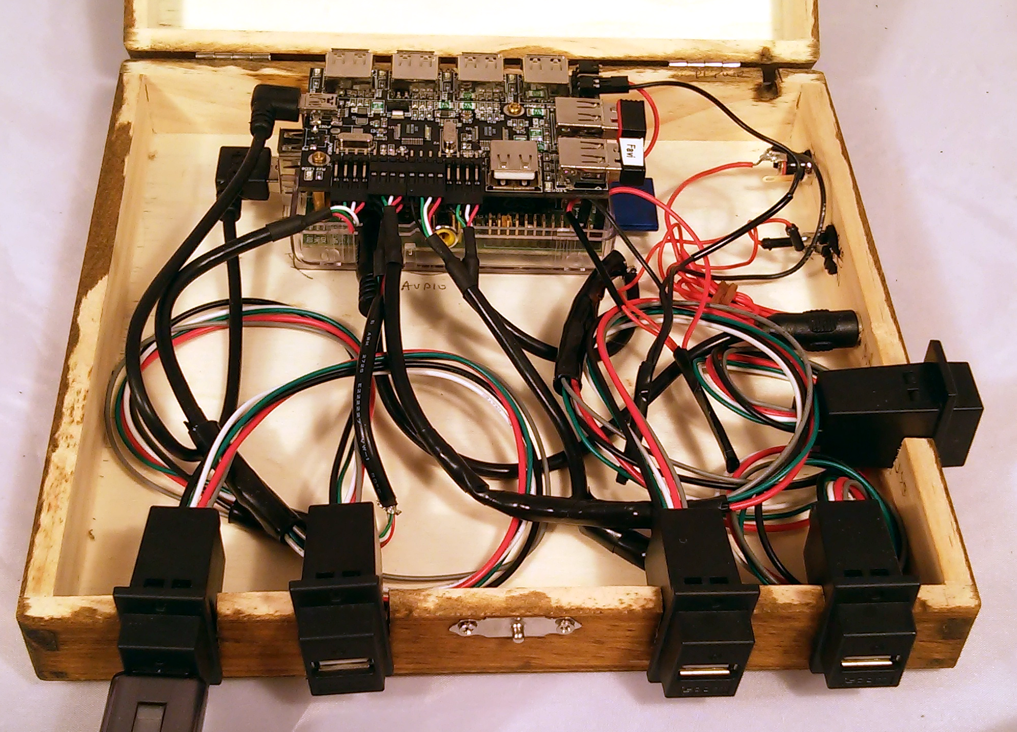
Inside the case we see the Pi/Hub component at the back with USB cables routed to the front and side panels. These cables were hard to find. Most USB connectors do not have the small plastic edge to hold them in place like these do. The cables were cut and soldered to 4 pin connectors, and the solder joints wrapped in electrical tape. The soldering of the second cable on the left is bad and will have to be redone. The plastic case has a snap fit and allows me to use glue dots to hold it in place without affecting the Rasperry Pi. Velcro would have worked as well, but glue dots don't require you to be quiet so accurate when positioning in the box. Power is attached with a barrel connector at the back of the side panel. This splits and is run to the 5V input pins of the hub and the Pi separately. The hub should be able to power the Pi but tests shows that they operate more consistantly if they are powered separately. The power supply is 5V/4A and is plenty to support the wifi and keyboard dongles plus multiple media sticks. The input power ties to a power switch so the whole thing can be powered on and off at one point. The PiBox software is designed to run from memory, not from the SD card, so power-off and back on does not damage the filesystem.
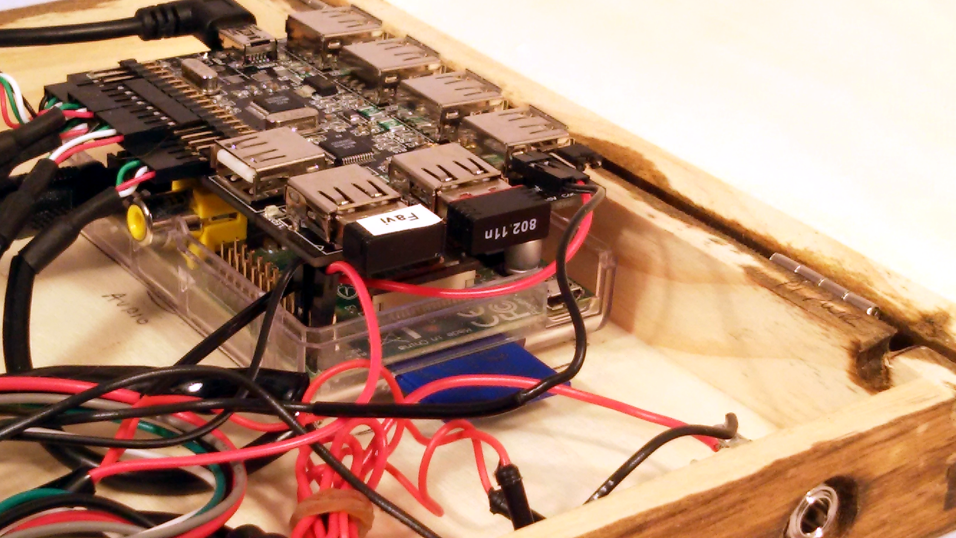
This is a close up of the power connectors. This was the biggest stumbling block in putting this project together. The hub should be able to power the Pi, but for some reason it couldn't do it. Also, if I split off the power and connected through the micro-USB A ports I got inconsistent results. Sometimes the Pi partially powered up, sometimes not at all. The only solution that constantly works is to connect the power input directly to the 5V pins on the Pi and the hub and disable the hub from trying to power the Pi. I should note that all my tests with an analog meter showed 5V to all test points. My meter didn't do amps, however. So I never could understand where the problem exists. But I managed to find a workaround. For a long time software nerd like myself, I've found that board layout (with tools like Eagle) is easy compared to making sure power is correct.
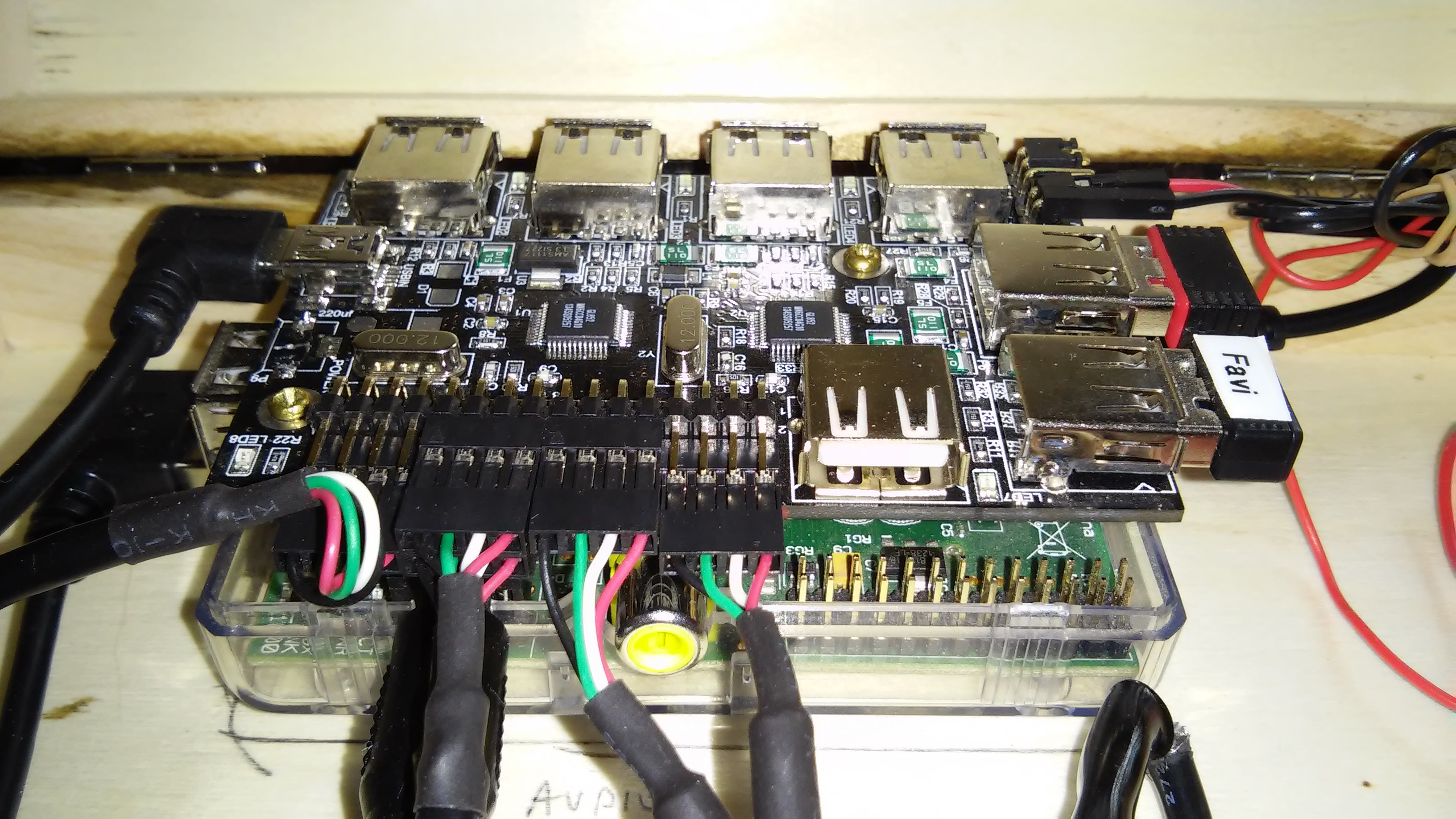
This image shows the use of power and USB pins and dongles on the hub and right angle USB cable connecting the hub to the Rasperry Pi.
PiBox Media Player
As of the 1.1.0 release the Media Player is no longer a separate system from the Media System.
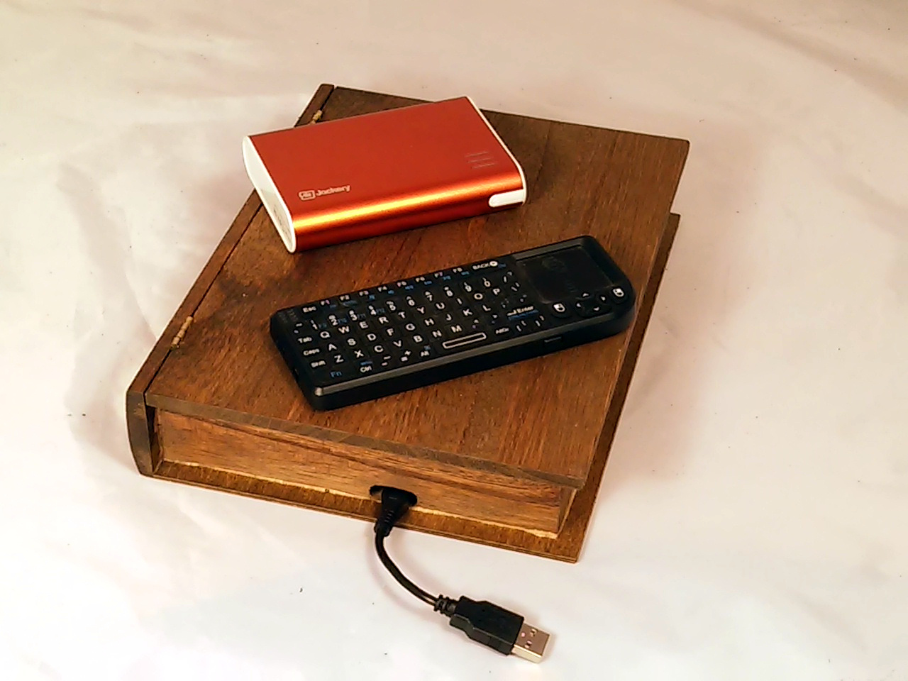
The PiBox Media Player was designed with the intent of being powered by battery. A Jackery Giant's 2A output port can power both the Raspberry Pi and pico projector inside. Like the PiBox Media System, the Media Player uses a wireless FAVI keyboard and wifi. The Media Player prototype box is made from a slightly different box, with a book-like shape. The bottom edge of the book (shown here) holds the power port while the top edge provides the projector port. The power switch is on the right side (not shown).
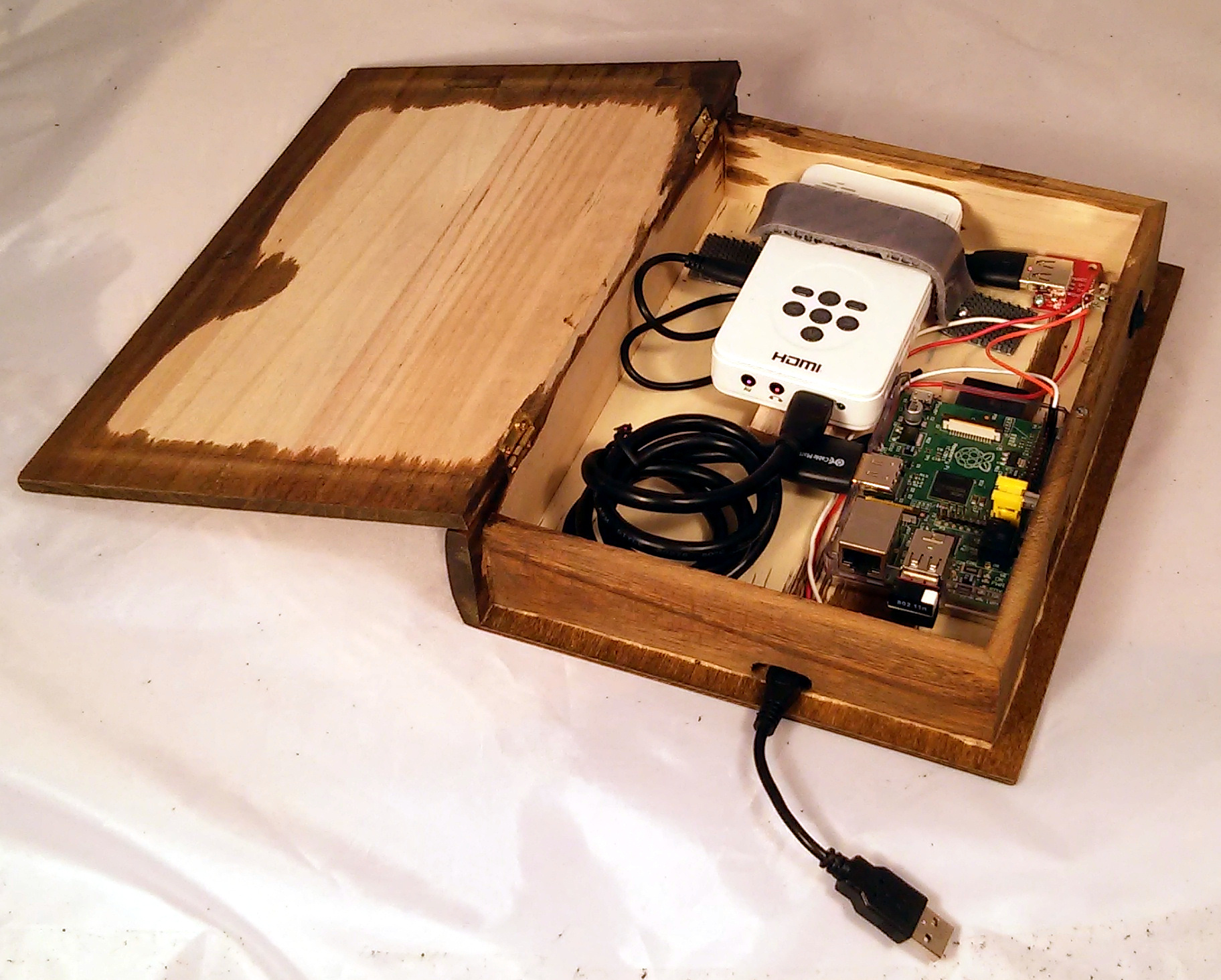
Inside the PiBox Media Player there is an AAXA Technologies projector connected via HDMI to the Raspberry Pi. In the upper right is a USB break-out board that is used to connect input power directly to the projector. That means when ever the power is connected the projector's builtin battery will be charged. The input power splits between the break-out board and the power switch. When the power switch is on then the Raspberry Pi boots. The problem with this scheme is that it takes two power switches to power the Media Player: the one on the side for the Raspberry Pi and the one on top (and inside the case) of the projector. The only way to fix this is to build my own projector. That's a projector for another day, one using a TI DLP chip no doubt. The HDMI cable is too long, but it's the shortest cable I could find. Making one by hand seemed a bit more complex than, say, a USB cable.
In Action
(:youtube tbd:)
|